Advanced Line Following Robot
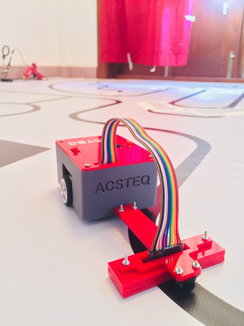
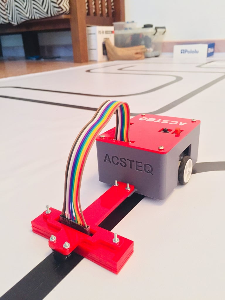
I designed and developed a high-performance autonomous line-following robot under my personal brand "AcsteQ", building both the embedded system architecture and mechanical platform over an eight-month development period. The system achieved a 100 ft traversal in 26 seconds (1.17 m/s) while maintaining stability across sharp curves and varying track geometries.
This project focused on real-time embedded control, latency minimization, and system-level performance optimization.
Software & Embedded Control Architecture
The robot operates on a real-time feedback control system built around a PID (Proportional–Integral–Derivative) algorithm. The controller continuously computes an error value based on line deviation and updates motor outputs through PWM modulation.
The three PID components were carefully tuned:
Proportional (Kp): Managed immediate corrective response to positional error.
Integral (Ki): Eliminated steady-state drift and accumulated tracking bias.
Derivative (Kd): Reduced overshoot and dampened oscillations during high-speed directional changes.
Extensive iterative testing was conducted to optimize gain values under different track conditions. The final tuning enabled stable high-speed tracking without oscillation, overshoot, or instability.
To complement directional correction, I implemented a dynamic speed control algorithm using a switch-case logic structure. Speed was controlled via 8-bit PWM (0–255), enabling precise motor output modulation.
The control logic dynamically:
Increased speed during low-error straight-line conditions
Reduced speed proportionally to error magnitude
Transitioned smoothly between velocity states to prevent abrupt mechanical stress
Recently, I integrated a lightweight ML-based enhancement layer to further smooth motion transitions and improve adaptive behavior under rapid curvature changes. This system required careful timing coordination between sensor sampling, PID computation, and PWM updates to ensure low-latency control response.
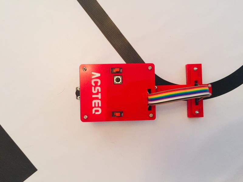
Hardware Architecture
The embedded system was designed to prioritize fast sensor-to-actuator response and electrical stability. Key engineering considerations included:
Real-time microcontroller-based processing
High-speed motor driver interface for PWM-based control
Optimized sensor array placement for accurate positional feedback
Stable power distribution to prevent voltage drop under load
Particular focus was placed on minimizing control latency and electrical noise, as even small delays or signal instability can cause oscillation at high velocities. The system architecture ensured deterministic control behavior, allowing consistent performance across repeated trials.
Mechanical System Integration
The chassis and drivetrain were engineered to support high-speed stability and consistent traction. Mechanical optimization included:
Balanced weight distribution for reduced inertia shift
Low-vibration structural alignment
Precise sensor mounting geometry
Drivetrain tuning for rapid acceleration without loss of control
Mechanical and embedded control systems were co-optimized to ensure predictable system dynamics, especially during sharp directional transitions.
Firmware & Systems Perspective
From a firmware standpoint, this project required designing a deterministic real-time control loop where sensor acquisition, PID computation, and PWM motor updates were executed with minimal latency. Stability at high speed depended on precise timing, efficient interrupt handling, and consistent control cycle execution.
By optimizing embedded software, electrical design, and mechanical dynamics, I was able to build a tightly integrated system where control logic translated predictably into physical motion. This project strengthened my understanding of low-level embedded control, timing-sensitive systems, and performance tuning in resource constrained environments.